Sony ICF-SW100 Ribbon Cable Failure -- Frequently Asked Questions
I have owned a Sony ICF-SW100 since 1994. This shirt-pocket-sized world band receiver has been my companion on numerous trips to the USA, Europe, the Middle East and Asia. I continue to use it every day, both for shortwave and domestic FM reception.
Unfortunately, as many owners of this receiver have found, units produced before autumn of 1997 have a weakness: the ribbon cables connecting the upper and lower sections of the receiver eventually fail, causing many problems including inability to use any or all of the buttons on the keyboard, including the on/off buttons.
When this happened to me, I was not at all happy. However, I found some information on how to correct the problem on the Internet and was able to fix the trouble myself. I subsequently decided to collect in one place the information needed to effect the repair.
Much of the information in the "How to Repair" section was originally presented by jpd (at) space.mit.edu (John Doty) on the newsgroup rec.radio.shortwave. The remainder comes from my experiences, together with supplementary information submitted by various correspondents from time to time.
I would be pleased to receive any additions or corrections to this material.
Updates:
22-Nov-2001: Sony UK contact information.
04-Sep-2001: Sony now offers a repair kit for those older model receivers that are susceptible to the problem discussed here (Sony has modified the design in receivers manufactured after late 1997.)
NOTE: This problem was addressed by Sony in a major revision of both the SW100 and SW77 in the autumn of 1997. (Thanks to Lee Rothman for this information.) I have not received reports of failures of units incorporating the design change. According to one correspondent, the newer models may be identified by the fact that no copper is visible on the ribbon cables when viewed through the gap in the hinge -- the cable is protected by a black plastic layer.
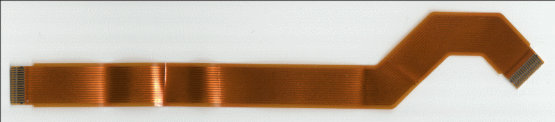
The upper and lower modules of the SW100 are interconnected by two ribbon cables, or "Flexible PC Boards" as they are called in the Sony service manual parts list. The microprocessor that controls the operation of the receiver is in the lid assembly, and its interface to the keyboard and receiver electronics in the base (or "chassis") assembly passes through these cables.
The edge of the plastic at the point on the lid module where the ribbon cables exit is very sharp. In a test, it functioned as an efficient wire cutter for 30-gauge bare copper wire. When the lid is closed, the inner ("Key") ribbon cable is pulled taut and makes a bend of over 90 degrees with a bending radius of, essentially, zero.
Copper does not forgive this sort of insult. Over time, the key ribbon cable will develop breaks in the copper conductors, which will cause various keys on the keyboard to stop working, including the on/off switch. The Signal ribbon cable may also develop problems -- I have observed this in one case so far.
[Back to top]You can check the condition of the ribbon cables by disassembling some parts of the receiver as described below, and inspecting the conductors.
If you have the correct screwdriver, you may separate the lid portion from the base (chassis) portion to look at the cable; if not, you may disassemble the upper and lower halves of the receiver and remove the cables from the receiver for inspection.
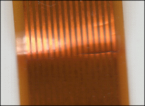
The break in the conductor may be very difficult to see -- nothing more than a slight discoloration of the copper at the point of the break.
In the case shown here, the break is rather obvious:
NOTE: The new Sony repair kit discussed below contains a new lid main moulding; it would appear that installing this piece should make it unnecessary to modify the old lid as described in this section.)
Separating the lid and base assemblies of the receiver gives you the opportunity to use a small file to dull the extremely sharp edge that causes the fatal bend in the conductor. This should prevent (or at least delay the onset of) the failure.
The lid assembly is fastened to the base assembly by two long screws requiring a small (about 0,7 mm) cross-point screwdriver. They are made of soft metal and it is very easy to damage these screws with incorrect tools or careless operation.
The upper lid portion disassembles easily, as the two halves snap together. The ribbon cables slip into two sockets on the circuit card. The sockets have locking strips that should be released before removing or inserting the ribbon cable.
[Back to top]Part no. = X-3372-340-1 Desc. = kit mcb, flexibleThis is a complete kit to bring a mk1 unit up to mk2 spec, it includes a new lid main moulding, 2 cables and the stick on vinyl flexible cable protector. Cost in the UK about 15 pounds including tax.
  1-651-256-11 PC BOARD, FLEXIBLE (KEY)
  1-651-257-11 PC BOARD, FLEXIBLE (SIGNAL)
According to Ian, ordering either of these part numbers will now get you the repair kit.
It is possible that both cables may have developed
defects; the "Key" cable is the most likely to have been
damaged, as it is in contact with the sharp plastic edge.
You may find it advisable to replace both cables.
The steps: (NOTE: this sequence does not reflect changes
that may be necessary when installing the new repair kit.
Anyone who can provide update information on this is welcome to do
so.)
The cover of the lid is held on only by plastic claws, so it is easy to remove. The lower (chassis) portion has four screws in addition to claws: remove the screws identified by arrows on the bottom piece. The fifth screw you'll see (with no arrow) anchors the whip antenna: it need not be removed. Once you've removed the screws and unhooked the claws, the chassis separates into three pieces: the upper part consisting of the lid, the top of the battery case, and the keyboard cover; the middle part holding the two circuit boards; and the lower cover.
The flexible boards plug into connectors on the circuit boards, so no soldering is necessary. The connectors into which the ends of the flexible circuit board slide are fitted with a bit of white plastic which is a lock/release mechanism. Before pulling out the damaged flex board, pull out the lock/release piece on the connector.
The boards are routed through a slot by the lid hinge. They only move freely when the lid is open: with the lid closed they are tightly pinched (this is the origin of the problem).
Be sure to fold the replacement the same way the original was folded. The silvered fingers on the end go toward the board when you plug it into the connector. When inserting the replacement part, be certain that the lock/release piece is pulled out; the flex board will then slide into the connector quite easily. When it is seated, push the lock/release piece into the connector.
As is usual with Sony products, reassembly is a bit like trying to line up a dozen live worms. Getting the plastic keys and the Main Power toggle to stay in place while you snap the chassis together is tricky, especially with the lid open to keep the flexible boards from jamming. Once the chassis is snapped together, the rest is easy.
[Back to top]